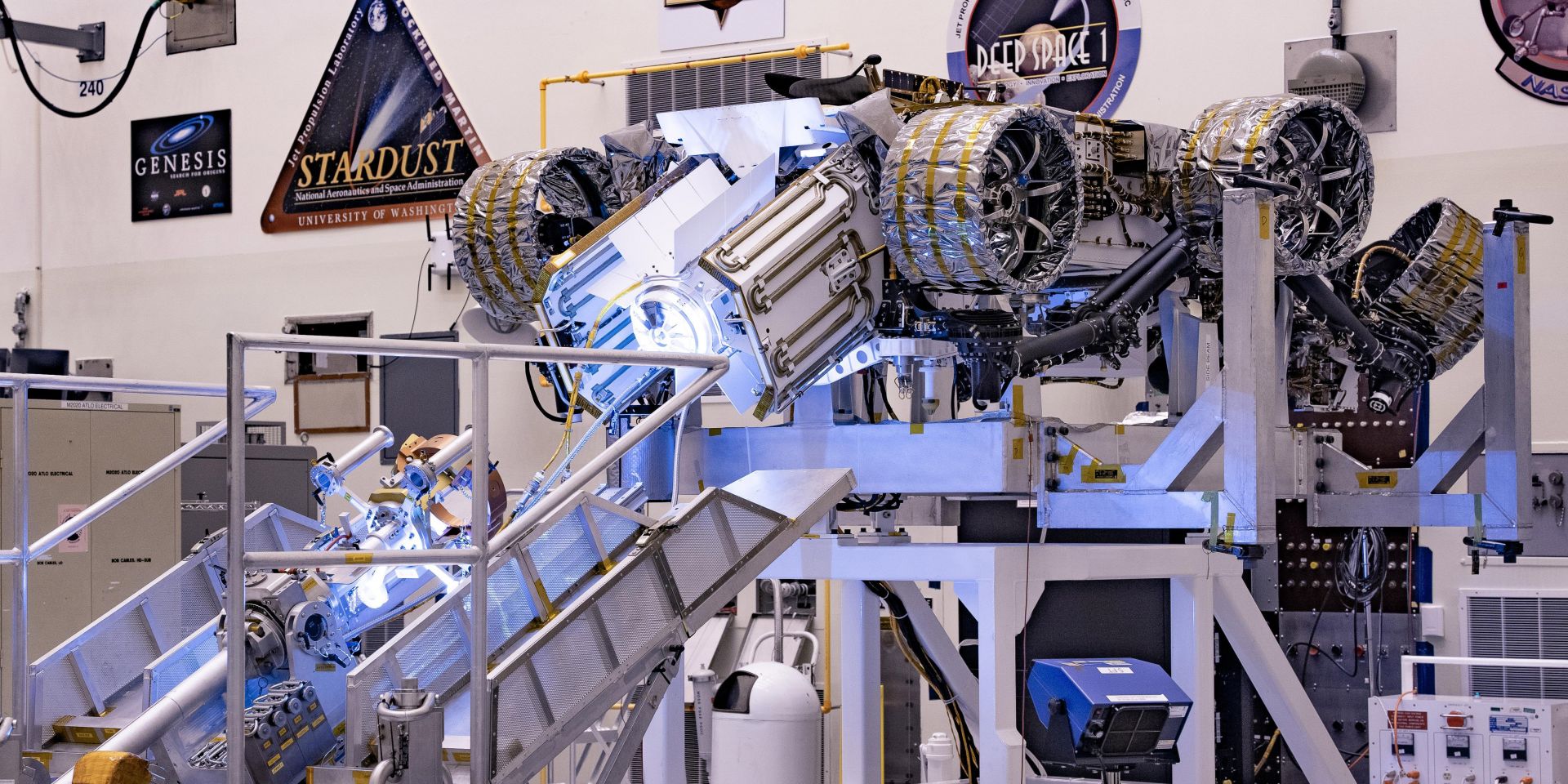
The multimission radioisotope thermoelectric generator for NASA’s Mars 2020 Perseverance rover is tested at NASA’s Kennedy Space Center in 2020. The choice of an MMRTG as the rover’s power system gave mission planners significantly more flexibility in selecting the rover’s landing site and in planning its surface operations. (Photo: NASA)
Under the Radioisotope Power Systems Program, NASA and the Department of Energy have been advancing a novel radioisotope power system (RPS) based on dynamic energy conversion. This approach will manifest a dynamic RPS (DRPS) option with a conversion efficiency at least three times greater than a thermoelectric-based RPS. Significant progress has recently been made toward this end. A one-year system design phase has been completed by NASA industry partner Aerojet Rocketdyne, which resulted in a DRPS with power of 300 watts-electric (We) with convertor-level redundancy. In-house technology development at the NASA Glenn Research Center (GRC) has demonstrated the conversion devices in relevant environments and has shown all requirements can be met. Progress has also been made on the control electronics necessary for dynamic energy conversion. Flight-like controllers were recently upgraded and achieved an 11-percentage-point increase in efficiency. Control architectures have been developed to handle the multiconvertor arrangements in the latest DRPS design. A system-level DRPS testbed is currently being assembled that will experimentally demonstrate the DRPS concept being pursued.
Background
NASA has been pursuing an RPS based on dynamic energy conversion for many years.1,2 The prior effort, advanced Stirling radioisotope generator (ASRG), culminated in verification testing of an engineering unit. Qualification unit assembly had begun when the project was canceled in 2013. Soon after this, in 2016, the pursuit of dynamic RPS was revitalized with a concentration on lessons learned from the ASRG project. Some important lessons learned that steered the revitalized effort were reducing the required system-level conversion efficiency to 20 percent, identifying and implementing methods of robustness in the conversion devices, and defining requirements early. Several dynamic convertor development efforts were initiated in 2017 to design, build, and test various viable technologies. These contracts are now complete, and several dynamic convertors have been delivered to NASA GRC. Sunpower provided four gas-bearing Stirling-cycle convertors, Infinia Technology (which has since been acquired by American Superconductor) provided two flexure-bearing Stirling--cycle convertors, and Creare produced one Brayton-cycle convertor. The Stirling-cycle convertors are currently undergoing independent validation and verification in the Stirling Research Laboratory at NASA GRC, while the Brayton-cycle device has remained at Creare for further experimentation with government-furnished equipment.
These convertor development contracts were augmented near their midpoints to produce system-level designs based on each. Each convertor provider partnered with a system integration contractor to produce a draft DRPS. The results of this design study were encouraging, showing that RPS-level requirements could be met. With this, and the successful demonstration of the convertors on multiple fronts, the decision was made to move forward with a flight-system development contract.
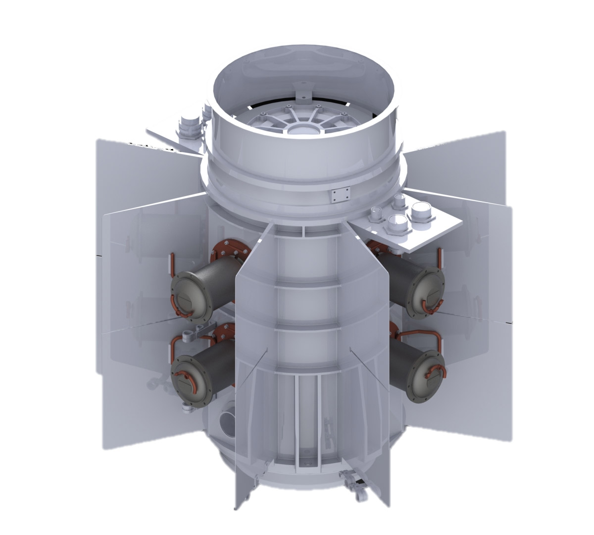
Fig. 1. Aerojet Rocketdyne’s 300-We-class lunar-qualified DRPS with convertor-level redundancy. (Image: Aerojet Rocketdyne and Sunpower)
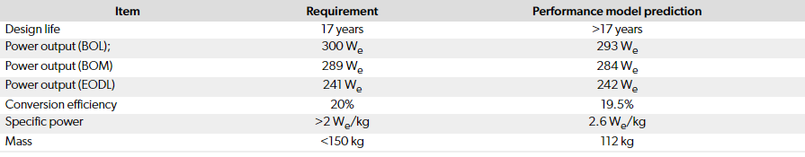
In late 2021, Aerojet Rocketdyne was awarded a one-year design contract under the jurisdiction of the DOE to develop a DRPS that would be suitable for multiple mission destinations and would be focused on qualification for first use on a lunar mission. The requirements for this effort are shown in Table 1. Lunar destinations to the polar regions are favorable for heat rejection, but those near the equator are difficult and drive the overall thermal design of the DRPS.
The design status review, which summarized this one year of work, including the trades, decisions, mechanical design details, and performance estimates, was held in December 2022. The design (Fig. 1) makes use of eight Sunpower Robust Stirling Convertors (SRSCs), Sunpower’s latest design, which manifested during NASA’s aforementioned convertor development contracts awarded in 2017. The convertors surround a
Flight-capable DRPS
In late 2021, Aerojet Rocketdyne was awarded a one-year design contract under the jurisdiction of the DOE to develop a DRPS that would be suitable for multiple mission destinations and would be focused on qualification for first use on a lunar mission. The requirements for this effort are shown in Table 1. Lunar destinations to the polar regions are favorable for heat rejection, but those near the equator are difficult and drive the overall thermal design of the DRPS.
The design status review, which summarized this one year of work, including the trades, decisions, mechanical design details, and performance estimates, was held in December 2022. The design (Fig. 1) makes use of eight Sunpower Robust Stirling Convertors (SRSCs), Sunpower’s latest design, which manifested during NASA’s aforementioned convertor development contracts awarded in 2017. The convertors surround a centrally located six-module heat source stack. This arrangement provides one redundant pair of convertors and thus would tolerate complete failure of two convertors and still maintain the required power output and efficiency by throttling up the surviving convertors. The mechanical design shares many elements with Aerojet Rocketdyne’s multimission RTG (MMRTG). The centrally located heat source enables efficient capture of the module heat and permits the same tooling to be used by the DOE during the critical fueling process. The use of a heat source liner is also possible here to protect the modules from mission destinations with atmospheric content, such as carbon monoxide and carbon dioxide on Mars. The SRSCs themselves require no protection from atmospheric constituents, as they are capable of operation without detriment even in a worse-oxidizing atmosphere on Earth.
The overall DRPS performance model predictions are quantified in Table 1. Performance models were based on the real-world SRSC performance measured by Sunpower rather than model predictions. A comprehensive thermal model of the DRPS was constructed and exercised for all mission scenarios referred to in the requirements. This included the worst-case thermal environment encountered at the Moon’s equator, with conservativism incorporated for dust accumulation on the radiating surfaces. This model showed that heat pipes linking the rejection zone of the SRSCs to the radiating surfaces were a favorable trade. The thermal model was also exercised for the scenarios in which a convertor pair has failed, which has the effect of increasing the heat flux throughout the remainder of the generator, thus is an important situation to quantify. Furthermore, the exercising of the model revealed which pair of failed convertors resulted in the worst-case thermal scenario. Performance estimates were generated for this matrix of cases. The model showed that the design in its current state would be capable of a lunar mission to within 35° of the equator. Future design adjustments could enable operation at the lunar equator. These thermal models of the lunar surface incorporate the latest data from recent spacecraft that have shown it to be hotter than estimates in the past.3
A structural model was created to show the design meets the structural requirements. The model was exercised to show compliance with requirements for launch random vibration (7.7 grms), and static acceleration (20 g). The model even evaluated the magnitude of disturbance forces that would be imparted on the spacecraft, including off-nominal situations in which the phase between paired convertors is deliberately nonzero, and the situation of a failed pair of convertors. This analysis showed there would be no difficulty reducing the residual disturbance emitted to an attached spacecraft below the requirement of 10 N.
The decision was made to use Sunpower’s SRSC as the conversion device for various reasons. Among the options, the SRSC1 has the highest specific power and improved on the predecessor under ASRG (Sunpower’s Advanced Stirling Convertor, or ASC). The piston incorporates a centering spring, so any chance of operator error during the start-up sequence is eliminated. The hot-end material is Haynes 230, a wrought alloy, which eliminates all the difficulties encountered with microcast 247-LC of the ASC, but has the creep properties necessary for long device life. The SRSC has features that eliminate contact between moving parts, even in the case of an unloaded alternator, so there is no concern of operational error causing damage to internal parts. The gas bearing capacity is increased, enabling the SRSC to handle the latest static acceleration environments that were not originally part of the ASRG effort. The magnets of the alternator are encapsulated by metallic structure, which is a significant improvement in robustness over the exposed-magnet arrangement of the ASC. This eliminates any possibility of magnet damage in the case of an overstroke situation. The regenerator is fabricated from a screen stock material, rather than a random fiber stock. This has recently been shown to eliminate debris shedding, which was an area of concern in the ASC. The recent completion of SRSC-4 showed no debris generation during inspections throughout Sunpower’s verification test sequence. As a backup, the gas bearing supply volume inlet has a small inlet filter, which would prevent disruption to the gas bearings even if some debris were released. Furthermore, the decision to use the SRSC was also driven by an examination of future production of a necessary number of convertors, in which Sunpower was deemed the most viable.
This design phase also included development of controller architectures that can handle the eight-convertor arrangement, while having component redundancy within the controller hardware itself. The controller must not only convert the alternating current output to direct current (for the spacecraft) but also must maintain stability of the convertor cycle in all mission scenarios. A topology was arrived at that achieves redundancy in the critical components, such as the active H-bridge rectifier, but does not require the large mass penalty of a 2x redundancy scheme. The design of the controller is detailed such that parts could be identified, board layouts have been designed, and mass estimates have been made.
Aerojet Rocketdyne’s one-year DRPS design phase attained a level of detail sufficient for the creation of interface control documents and manufacturing drawings. The path to a preliminary design review is straightforward from this point. With this, the risks deserve discussion but are understood and slated for mitigation as follows. The operating temperature of the modules in the DRPS is higher than that of the MMRTG and must be accommodated. The residual forces acting on the convertors (from any heat collector device on the hot end or the stacking of the surrounding insulation) must be quantified and accounted for. The exposed portions of the SRSCs are vulnerable to micrometeoroid damage and may require shielding. The controller electronics have a job more complex than any predecessor DRPS design. They must be capable of detecting convertor failure, disabling the failed convertors, and the timely throttling up of the survivors. This type of logic needs to be developed and demonstrated.
In-house generator development
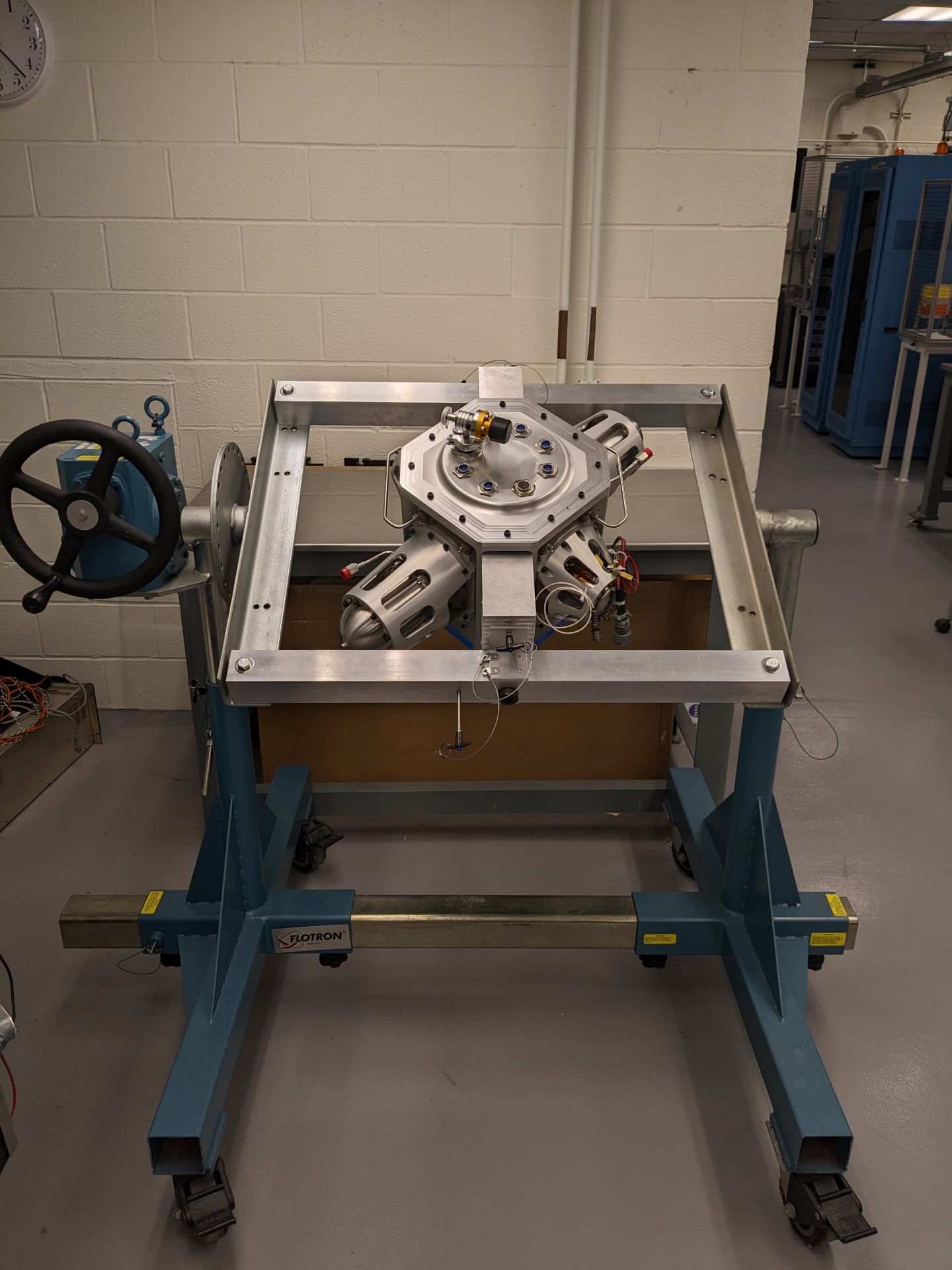
Fig. 2. NASA GRC’s DRPS testbed, which was developed in-house. (Photo: NASA GRC)

Fig. 3. Section view of NASA GRC’s DRPS testbed. (Image: NASA GRC)
In parallel with the convertor development work and generator design work by Aerojet Rocketdyne, the Thermal Energy Conversion branch at NASA GRC has been making strides toward demonstrating the latest DRPS topology via hardware tests. A DRPS testbed (Fig. 2) being assembled now that enables a four--convertor-system demonstration was conceived as a flexible test article, capable of operating with a range of Stirling convertor hardware, including legacy convertors from past projects as well as the most recent designs such as the SRSC. This unique test item permits a range of experimental investigations that would not be possible with the other extended operation test setups that already exist in the Stirling Research Laboratory at NASA GRC. The most important investigations with the testbed will include interactions and dynamics associated with operating more than one pair of convertors, radiant heat transfer from the centrally located heat source, and analyzing behaviors during simulated fault situations.
The requirements for the testbed were formulated with the goal of validating the proposed topology for a DRPS. The first requirement was that the Stirling convertors must be arranged in an arrayed layout with coplanar, dual-opposed pairs. In addition, the testbed must be capable of operating with either two or four Stirling convertors installed. The details of the final testbed design are illustrated in Fig. 3. In the center is a singular heat source that is radiantly coupled to the hot ends of the convertors. The heat source is capable of simulating either two or three general--purpose heat source modules and is identical in size and form to a stack of three modules. The housing is capable of dissipating all the waste heat from the system while maintaining the cold end of the Stirling convertors at or below 100°C in both ambient natural convection and in a thermal vacuum with a liquid nitrogen cold wall. There is also a provision for manipulating the cold-end temperature independently of the natural convective cooling via a coolant channel integral to the plate between each convertor and the housing. The fins attached to the housing are removable to enable experimentation with various sizes and materials. The housing interior has the capability to either be filled with up to 10 psig of inert cover gas or be evacuated. To account for a possible testing scenario where a single convertor is shut down (rather than a dual-opposed pair), there are features to attach a passive balancer in the same axis as each convertor’s piston motion.
After a lengthy part fabrication period, all hardware was delivered in August 2022, and assembly began. Significant time was spent attempting to seal leak paths through the cold side flanges of the convertors, to enable evacuation of the interior of the housing. These flanges were not designed to seal in the manner used in the testbed, and this was a known risk. After attempts to seal the various leak paths failed, the interior-vacuum option was abandoned, as a sufficient vacuum could not be achieved to give confidence for long-term operation. At room temperature (without the housing at the design operating condition), the best achievable vacuum was 5.2 × 10⁻⁴ torr. With graphite components inside that require protection from oxygen, this was deemed inadequate. The baseline option of filling with an inert cover gas (argon) will be employed. The testbed has passed a test to confirm its ability to contain the inert cover gas sufficiently, and the team is now executing the final assembly procedure.

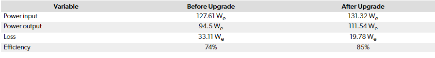
Fig. 4. Isolation stand and data acquisition rack for DRPS testbed. (Photo: NASA GRC)
The stand and test equipment rack (Fig. 4) are both complete, checked out, and verified ready for use. The task of designing the equipment rack was a unique challenge, as this version must support operation of four Stirling convertors, whereas the standard equipment rack at the Stirling Research Laboratory is designed to handle just two convertors. The stand consists of a three-axis isolation mount, based on linear slide rods for the x- and y-axes and rubberized vibration isolators for the z-axis. This mounting scheme permits near-zero-rigidity mounting of the testbed, which is necessary to measure and characterize the residual disturbance from any convertor imbalance present. The current testbed assembly iteration has two different types of Stirling convertors, but this was done only out of convenience. These units from predecessor projects (ASRG) were idle in storage and are being resurrected for this purpose in the testbed. Future assembly iterations are planned to incorporate four hermetically sealed SRSCs.
The testbed enables a range of unique tests that are not possible with the other test articles at the Stirling Research Laboratory, which isolate the convertors in a non-system-like assembly. The planned test sequence for the testbed is as follows:
Baseline performance measurement—Operate at a condition in which the four convertors are accepting heat from a 500-Wth source, maximize power output.
Thermal insulation loss characterization—Experimentally measure the amount of heat lost from the source that does not get taken by the convertors.
Convertor pair failure simulation—Deliberately stall one pair of convertors, and throttle the remaining pair to maintain power output.
Performance optimization—Explore the methods for maximizing system efficiency while the heat source decays (can be constant convertor hot-end temperature, or constant piston amplitude).
Off-nominal thermal environment—Explore the effect on performance when the heat rejection is not uniform among the four convertors, such as when one side is facing the sun and the other deep space.
Launch ascent simulation—For the case where the cover gas is vented during launch ascent and the DRPS will be used solely in vacuum, explore the thermal transient that results from cover gas removal during launch ascent and any necessary operating point adjustments.
Phase range characterization—Deliberately force the phase of the convertors to be off nominal, to explore the effect on residual disturbance force.
Controller development
Unlike a thermoelectric-based RPS, the DRPS requires a controller to maintain stability of the convertors and convert AC power output from Stirling convertors to 28 Vdc for the spacecraft. NASA GRC has been working with the Applied Physics Laboratory at the Johns Hopkins University for many years to develop several controllers, including the single convertor controller (SCC) and dual convertor controller (DCC).4,5 The SCC was developed to control one ASC in 2011 and has operated with an ASC for 8 years without issue. The DCC was developed in 2015 to control a pair of ASCs in a dual-opposed arrangement and was recently upgraded to improve efficiency by changing the H-bridge control algorithm from two-level switching to three-level switching.6 Testing in the laboratory with a pair of ASCs showed the efficiency improved from 74 percent to 85 percent, as shown in Table 2.
To reduce cost, minimize design complexity, and potentially resolve issues found in digital controllers, the capless NASA analog controller (NAC) was also developed and tested at NASA GRC. This controller uses active power factor correction (PFC) to maintain stability of the convertors and a DC/DC converter to produce 28 Vdc output, just like the SCC and DCC. Signal computations for the PFC and the DC/DC convertor, however, are performed using discrete components rather than programmable integrated components such as the field-programmable gate array. A demonstration of the capless NAC with an ASC was performed successfully, and the test setup is shown in Fig. 5.
Fig. 5. A test setup of the capless NAC with an ASC. (Photo: NASA GRC)
While active PFC is a preferred control method due to smaller size and volume, NASA GRC is also considering a passive PFC method to provide a backup option for the controller because a passive PFC method is simple and potentially more reliable. As part of this effort, NASA GRC is planning to perform an accelerated life testing of flight AC capacitors, M83421/02 (Fig. 6). While M83421/02 has life-testing data with DC voltage, no life-testing data are available to show capability for the 17-year design life with AC voltage. Therefore, this test will provide reliability data for passive PFC controllers.
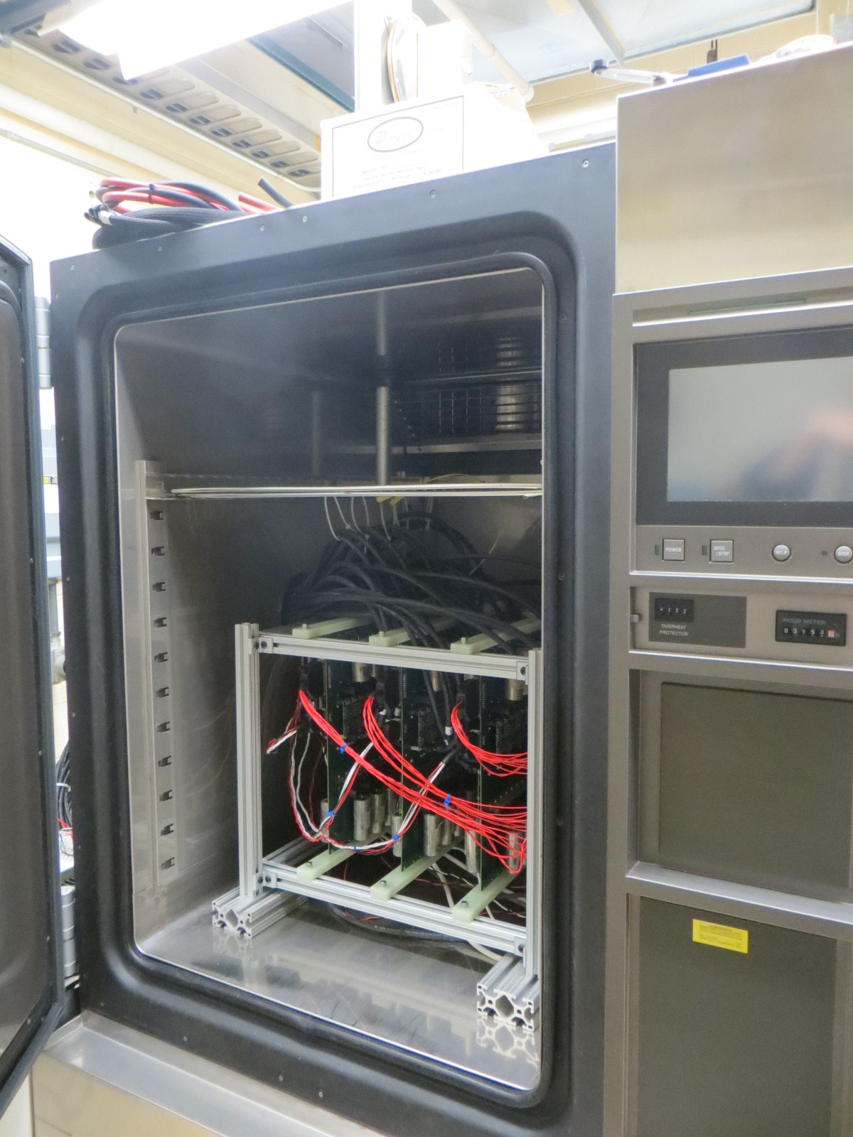
Fig. 6. A test setup of the flight capacitor accelerated life testing. (Photo: NASA GRC)
NASA GRC has created a multiconvertor configurable simulator (MCCS) to aid DRPS controller development (Fig. 7).7 This is a hardware-in-the-loop–based AC power source that can be programmed to behave like any sub-kW Stirling convertor, using linearized convertor models. The MCCS can simulate up to four convertors at a time and will be a valuable stand-in to verify proper operation of controllers managing up to four convertors. An additional MCCS unit can expand the total number of simulated convertors to eight convertors to support the lunar-qualified DRPS development.
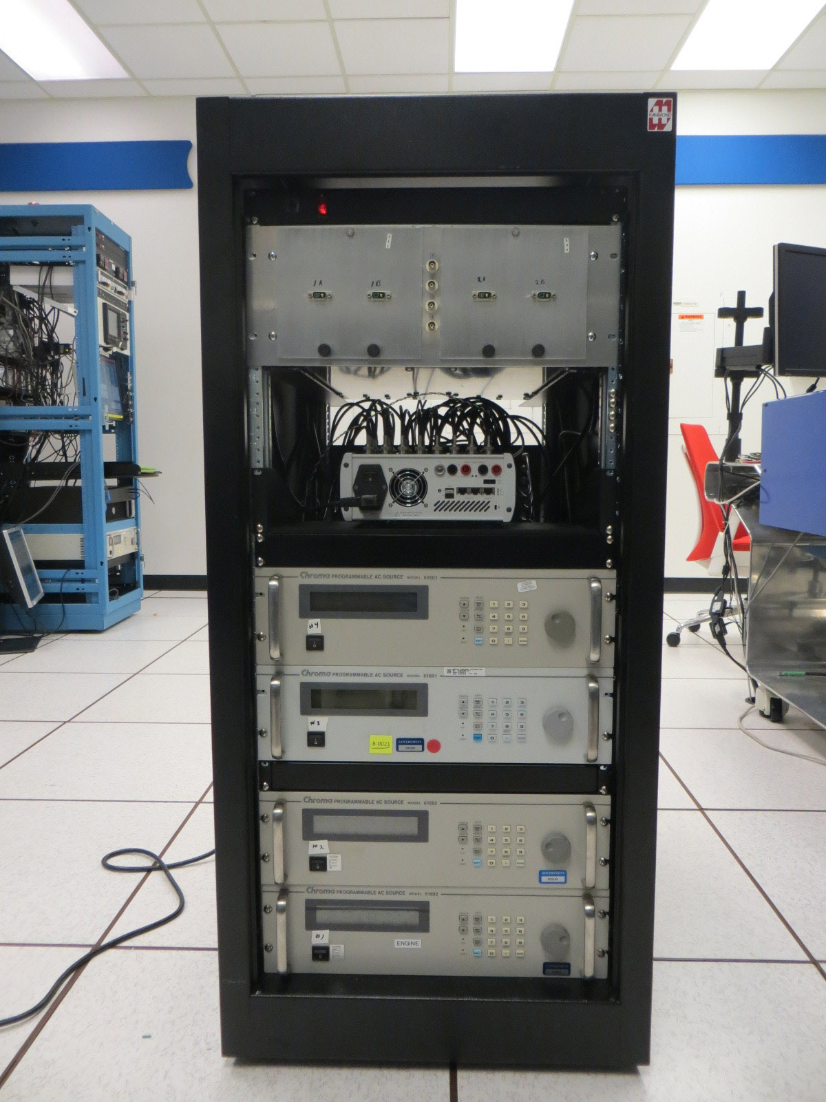
Fig. 7. Multiconvertor configurable simulator (MCCS) for controller development. (Photo: NASA GRC)
Conclusions
Large strides have been made recently toward a flight-capable DRPS that improves on the prior attempts by embracing lessons learned. Several viable Stirling-cycle convertors have arrived at NASA GRC and have undergone relevant environment testing. In-house efforts to show the viability of the latest convertor-redundant DRPS topologies have made significant progress. The four-convertor DRPS testbed is being assembled now, and testing is planned for spring 2023. A suite of tests is planned that will show all the unique features of this DRPS design, including the ability to maintain generator performance after a pair of convertors is turned off.
Progress has also continued in the development of controller electronics. An engineering unit controller capable of managing a pair of convertors was recently upgraded and resulted in an efficiency improvement from 74 percent to 85 percent. NASA GRC has developed a multiconvertor configurable simulator that can simulate four convertors of any variety at a time. Candidate flight-capable capacitors will soon be placed on an accelerated life test to demonstrate their viability for a 17-year mission. A one-year design phase with Aerojet Rocketdyne resulted in a DRPS design that can meet the requirements and has a straightforward path to preliminary design review. The performance model from this effort shows a convertor-redundant DRPS that produces almost 300 We at a conversion efficiency of 19.5 percent, with potential design changes that can improve performance further.